Piping (engineering): Difference between revisions
imported>Milton Beychok m (Piping moved to Piping (engineering): For disambuguation purposes) |
mNo edit summary |
||
| (9 intermediate revisions by 3 users not shown) | |||
| Line 1: | Line 1: | ||
{{subpages}} | {{subpages}} | ||
{{Dambigbox|Piping (engineering)|Piping}} | |||
{{Image|Pipework.jpg|right|350px|Exaple of large-scale industrial piping.}} | |||
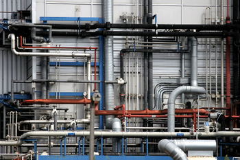
'''Piping''' is a system of [[pipe (material)|pipe]]s (hollow, cylindrical tubes) used to convey [[liquid]]s, [[gas]]es and sometimes other materials from one location to another within industrial facilities such as [[Petroleum refining processes|petroleum refineries]], [[chemical]] and [[petrochemical]] manufacturing, [[natural gas processing]], electricity-generating [[power plant]]s and many others. The adjacent photo depicts a complex piping system in an industrial plant. | '''Piping''' is a system of [[pipe (material)|pipe]]s (hollow, cylindrical tubes) used to convey [[liquid]]s, [[gas]]es and sometimes other materials from one location to another within industrial facilities such as [[Petroleum refining processes|petroleum refineries]], [[chemical]] and [[petrochemical]] manufacturing, [[natural gas processing]], electricity-generating [[power plant]]s and many others. The adjacent photo depicts a complex piping system in an industrial plant. | ||
Industrial plant piping and the accompanying in-line components can be manufactured from various [[steel]] alloys, [[titanium]], [[ | Industrial plant piping and the accompanying in-line components can be manufactured from various [[steel]] alloys, [[titanium]], [[aluminium]], [[copper]], [[glass]] or various [[plastic]]s. The in-line components are known as [[Piping and plumbing fittings|fittings]] and [[valves]]. | ||
[[Process control]] systems use in-line sensors and [[control valves]] installed in the piping to monitor and regulate the desired [[temperature]]s, [[pressure]]s, [[flow rate]]s and process vessel liquid levels of the fluids being transported and processed. Piping and control systems are documented in drawings referred to as [[Piping and Instrumentation Diagram]]s. | [[Process control]] systems use in-line sensors and [[control valves]] installed in the piping to monitor and regulate the desired [[temperature]]s, [[pressure]]s, [[flow rate]]s and process vessel liquid levels of the fluids being transported and processed. Piping and control systems are documented in drawings referred to as [[Piping and Instrumentation Diagram]]s. | ||
==Piping design== | ==Piping design== | ||
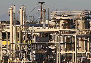
{{Image|Industrial piping.jpg|right|350px|Another example of large-scale industrial piping.}} | |||
The routing and layout of the pipes fittings in a complex piping system is typically done by experienced piping draftsmen known as ''piping designers''. The discipline of [[piping design]] does not require a university degree but it does requires a good many technical skills such as:<ref>{{cite book|author=James O. Pennock|title=Piping Engineering Leadership for Process Plant Projects|edition=|publisher=Gulf Professional Publishing|year=2001|id=ISBN 0-88415-347-9}}</ref> | The routing and layout of the pipes fittings in a complex piping system is typically done by experienced piping draftsmen known as ''piping designers''. The discipline of [[piping design]] does not require a university degree but it does requires a good many technical skills such as:<ref>{{cite book|author=James O. Pennock|title=Piping Engineering Leadership for Process Plant Projects|edition=|publisher=Gulf Professional Publishing|year=2001|id=ISBN 0-88415-347-9}}</ref><ref>{{cite book|author= R.H. Perry, R.H. and D.W. Green (Editors), |title=[[Perry's Chemical Engineers' Handbook]]|edition=8th Edition|publisher=McGraw-Hill Book Company|year=2007|id=ISBN 0-07-142294-3}}</ref><ref>{{cite book|author=John J. McKetta (Editor)|title=Piping Design Handbook|edition=|publisher=Marcel Dekker, Inc.|year=1992|id=ISBN 0-8247-8570-3}}</ref> | ||
<ref>{{cite book|author= R.H. Perry, R.H. and D.W. Green (Editors), |title=[[Perry's Chemical Engineers' Handbook]]|edition=8th Edition|publisher=McGraw-Hill Book Company|year=2007|id=ISBN 0-07-142294-3}}</ref><ref>{{cite book|author=John J. McKetta (Editor)|title=Piping Design Handbook|edition=|publisher=Marcel Dekker, Inc.|year=1992|id=ISBN 0-8247-8570-3}}</ref> | |||
* The principles and practice of drafting in general and of creating isometric drawings. | * The principles and practice of drafting in general and of creating isometric drawings. | ||
| Line 24: | Line 23: | ||
* A good understanding of [[pipe stress analysis]] | * A good understanding of [[pipe stress analysis]] | ||
Piping designers and pipe stress engineers are responsible for the proper placement of pipe hangers and pipe supports. They are also responsible for making sure that that the [[thermal expansion]] and contraction of the piping is compensated for and that the allowable pipe stresses are not exceeded under the appropriate design codes and standards.<ref>[http:// | Piping designers and pipe stress engineers are responsible for the proper placement of pipe hangers and pipe supports. They are also responsible for making sure that that the [[thermal expansion]] and contraction of the piping is compensated for and that the allowable pipe stresses are not exceeded under the appropriate design codes and standards.<ref>[http://www.asme.org/products/books/process-piping--the-complete-guide-to-asme-b31-3-- Complete Guide to ASME B31.3, Third Edition ] (published by the [[American Society of Mechanical Engineers]])</ref><ref>[http://catalog.asme.org/Codes/PrintBook/B311_2004_Power_Piping.cfm Power Piping: ASME B31.1] (published by the American Society of Mechanical Engineers)</ref> The checking of pipe stresses is usually done with the assistance of a computerized ([[Finite element analysis|finite element]]) pipe stress analysis program such as [[Caesar II]], [[ROHR2]], [[CAEPIPE]] and [[AUTOPIPE]]. | ||
==Plumbing== | ==Plumbing== | ||
| Line 34: | Line 33: | ||
==References== | ==References== | ||
{{reflist}} | {{reflist}}[[Category:Suggestion Bot Tag]] | ||
Latest revision as of 12:01, 4 October 2024
Piping is a system of pipes (hollow, cylindrical tubes) used to convey liquids, gases and sometimes other materials from one location to another within industrial facilities such as petroleum refineries, chemical and petrochemical manufacturing, natural gas processing, electricity-generating power plants and many others. The adjacent photo depicts a complex piping system in an industrial plant.
Industrial plant piping and the accompanying in-line components can be manufactured from various steel alloys, titanium, aluminium, copper, glass or various plastics. The in-line components are known as fittings and valves.
Process control systems use in-line sensors and control valves installed in the piping to monitor and regulate the desired temperatures, pressures, flow rates and process vessel liquid levels of the fluids being transported and processed. Piping and control systems are documented in drawings referred to as Piping and Instrumentation Diagrams.
Piping design
The routing and layout of the pipes fittings in a complex piping system is typically done by experienced piping draftsmen known as piping designers. The discipline of piping design does not require a university degree but it does requires a good many technical skills such as:[1][2][3]
- The principles and practice of drafting in general and of creating isometric drawings.
- Familiarity and experience with computerized drafting programs.
- The ability to visualize and develop an industrial facility plot plan.
- A basic understanding of fluid flow, piping materials and piping specifications.
- An extensive knowledge of piping standards and codes as well as process safety codes and practices.
- A knowledge of the various types of pipe connections such as threaded, welded and flanged connections as well as a knowledge of the various types of valves and why and where they are used.
- A good understanding of pipe stress analysis
Piping designers and pipe stress engineers are responsible for the proper placement of pipe hangers and pipe supports. They are also responsible for making sure that that the thermal expansion and contraction of the piping is compensated for and that the allowable pipe stresses are not exceeded under the appropriate design codes and standards.[4][5] The checking of pipe stresses is usually done with the assistance of a computerized (finite element) pipe stress analysis program such as Caesar II, ROHR2, CAEPIPE and AUTOPIPE.
Plumbing
Plumbing is a smaller-scale piping system that most people are familiar with because it is used to provide potable water and natural gas (or fuel oil) to their homes and businesses.
Plumbing systems in residential and commercial buildings also provide water to fire sprinkler systems, distribute hot water, route the refrigeration fluids used in air conditioning and remove sewage.
References
- ↑ James O. Pennock (2001). Piping Engineering Leadership for Process Plant Projects. Gulf Professional Publishing. ISBN 0-88415-347-9.
- ↑ R.H. Perry, R.H. and D.W. Green (Editors), (2007). Perry's Chemical Engineers' Handbook, 8th Edition. McGraw-Hill Book Company. ISBN 0-07-142294-3.
- ↑ John J. McKetta (Editor) (1992). Piping Design Handbook. Marcel Dekker, Inc.. ISBN 0-8247-8570-3.
- ↑ Complete Guide to ASME B31.3, Third Edition (published by the American Society of Mechanical Engineers)
- ↑ Power Piping: ASME B31.1 (published by the American Society of Mechanical Engineers)

